Для оформления заявки добавьте оборудование
в корзину и сформируйте заказ
Доставка в любой регион России транспортной
компанией на Ваш выбор
| Параметр | Значение |
| Общие характеристики | |
| Артикул | 3837 |
| Материал | wetted parts: - process connection and extension pipe: 1.4435/316L with ECTFE coating - vibration fork: 1.4435/316L with ECTFE coating housings: - polyester housing: PBT-FR with PBT-FR cover or with PA12 cover with sight glass, cover seal: EPDM - stainless steel housing: 1.4301/304, cover seal: silicone - aluminum housing: EN-AC-AlSi10Mg, plastic-coated, cover seal: EPDM cable gland: polyamide or brass, nickel-plated temperature spacer: 1.4435/316L flameproof bushing: 1.4435/316L |
| Control elements | electronic insert FEL50A (PA): 8 switches for device address setting electronic inserts FEL51 (AC), FEL52 (E5), FEL54 (WA), FEL55 (SI), FEL56 (N1): two switches for fail-safe mode and density change electronic insert FEL58 (N2): two switches for fail-safe mode and density change and one test button interrupts lead |
| Ambient temperature | -50 ... 70 °C (-58 ... 158 °F) , function with reduced data values see section ambient temperature |
| Storage temperature | -50 ... 80 °C (-58 ... 176 °F) |
| Degree of protection | polyester, steel, and aluminum housing: IP66/IP67 |
| Connection | electronic inserts: cross section max. 2.5 mm , lace in end splice in acc. with DIN 46228 ground lead in housing: cross section max. 2.5 mm external equipotential bonding: cross section 4 mm |
| Mass | 800 g , basic weight: compact version (length type II), electronic insert, plastic housing, without flange, additional weight is dependent on extension tube, housing and process connection process connections: - A3H 1000 g, A5H 1500 g, A6H 2400 g, A6I 3200 g, A8H 4900 g - H35 1400 g, H65 2400 g, H71 1600 g, H75 3200 g, H95 5900 g, HA3 5600 g - J1H 1700 g extension tube, temperature spacer, flameproof bushing: - BK* 900 g/m - CK* 2300 g/100 in - DKA 100 g, DKB 700 g, DKC 800 g |
| Rated voltage | electronic insert FEL50A (PA): 9 ... 32 V DC electronic insert FEL51 (AC): 253 V AC, 50/60 Hz electronic insert FEL52 (E5): 10 ... 55 V DC electronic insert FEL54 (WA): 19 ... 253 V AC, 50/60 Hz or 19 ... 55 V DC electronic insert FEL55 (SI): 11 ... 36 V DC, PLC electronic insert FEL56 (N1), FEL58 (N2): isolating amplifier acc. to EN 60947-5-6 (NAMUR) |
| Power consumption | electronic insert FEL52 (E5): max. 0.83 W electronic insert FEL54 (WA): max. 1.3 W |
| Switching point | see section switch point |
| Electromagnetic compatibility | NE 21 |
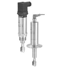
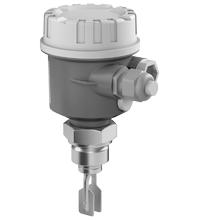
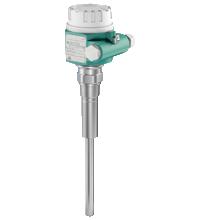
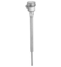
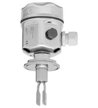
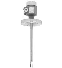
| Construction type | device with extension tube, coated with ECTFE |
| Measurement range | depends on mounting point and pipe extension up to 3000 mm , larger sizes on request |
| Reference operating conditions | ambient temperature: 23 °C (73.4 °F), medium temperature: 23 °C (73.4 °F), product density: 1 g/cm (water), viscosity: 1 mm /s, medium pressure p : 0 bar, sensor mounting: vertical from above, density switch: to > 0.7 g/cm |
| Maximum measured error | max. ± 1 mm, specified by mounting position |
| Vibration resistance | 10 ... 50 Hz, 0.15 mm, 100 cycles |
| Dimensions | housing: diameter max. 85 mm, height max. 173 mm temperature separator, flameproof bushing: additional length L 140 mm process connection: length L min. 115 mm extension: any length L from 148 ... 3000 mm, larger sizes on request extension: length type II, for vertical installation from above same switching point as Vibracon LVL2 vibration fork: width 20.6 mm, fork width 6.5 mm, length 25 mm |
| Process connection | flanges to EN 1092-1 from DN25, to ANSI B 16.5 from 1 inch, to JIS B 2238 (RF) from DN50 For further information see type code. |
| CSA approval | see control drawings (ZD) |
| Hysteresis | approx. 2 mm |
| Measuring method | The forks of the sensors vibrate at their intrinsic frequency. This frequency is reduced when covered with liquid. The change in frequency then activates the limit switch. |
| EU-type examination certificate | see instruction manuals (SI) |
| IECEx approval | see instruction manuals (SI) |
| Supplementary information | EC-Type Examination Certificate, Statement of Conformity, Declaration of Conformity, Attestation of Conformity and instructions have to be observed where applicable. For information see www.pepperl-fuchs.com. |
| Designation | see technical information (TI) |
| FM approval | see control drawings (ZD) |
| Display elements | electronic inserts: - electronic inserts FEL50 A (PA), FEL58 (N2): green LED, yellow LED - electronic inserts FEL51 (AC), FEL52 (E5), FEL54 (WA), FEL55 (SI), FEL56 (N1): green LED, red LED |
| Current consumption | electronic insert FEL52 (E5): max. 15 mA |
| Surge protection | electronic insert FEL51 (AC), electronic insert FEL52 (E5), electronic insert FEL54 (WA), electronic insert FEL55 (SI): overvoltage category III |
| Installation position | with short pipe (up to 500 mm (19.7 inch)) any position, with long pipe vertical |
| Switching delay | when fork is covered: approx. 0.5 s, when fork is exposed: approx. 1.0 s (other switching times on request) additionally configurable for PROFIBUS PA (electronic insert FEL50A (PA)): 0.5 ... 60 s |
| Directive 73/23/EEC | EN 61010-1 |
| Directive 89/336/EEC | EN 61326 If the fork tines are joined together on account of build-up, the useful signal is attenuated to such an extent that the original EMC values can no longer be completely observed (EN 61000-4-3 electromagnetic fields, EN 61000-4-6 HF coupling). |
| Measured variable | limit level (limit value) |
| Climate class | DIN EN 60068-2-38/IEC 68-2-38 |
| Non-repeatability | 0.1 mm |
| Influence of medium temperature | max. 1.4 ... -2.8 mm (-40 ... 120 °C (-40 ... 248 °F)) |
| Influence of medium pressure | max. 0 ... -2 mm (0 ... 40 bar) |
| Medium temperature | -50 ... 150 °C (-58 ... 302 °F) , exceptions see process connections |
| State of aggregation | liquid |
| Density | min. 0.5 g/cm , other density settings on request |
| Viscosity | max. 10000 mm /s |
| Solid contents | < ∅5 mm |
| Surface quality | R < 3.2 µm |
| Overspill protection | see approval (ZE) |
| Supplementary documentation | technical information (TI) manuals, brief instructions (BA, KA) instruction manuals (SI) control drawings (ZD) |
| Function principle | limit detection Maximum or minimum detection in tanks or pipelines containing all types of liquids including use in explosion hazardous areas. Particularly suited to very aggressive liquids thanks to high degree of corrosion protection. |
| Medium pressure | p = -1 ... 40 bar (-14.5 ... 580.2 psi) over the entire temperature range , exceptions see process connections |
| Switch behaviour | switch-over for minimum/maximum residual current safety on electronic insert MAX = maximum safety: The output switches to the power fail response when the fork is covered. for use with overspill protection for example MIN = minimum safety: The output switches to the power fail response when the fork is exposed. for use with dry running protection for example When switching on the power supply the output assumes the alarm signal. After max. 2 s it assumes the correct switching mode. |
| Influence of medium density | max. +4.8 ... -3.5 mm (0.5 ... 1.5 g/cm ) |
| Test pressure | max. 100 bar (1.5 times the medium pressure p ), no function during test pressure, burst pressure of diaphragm 200 bar |
| Thermal shock resistance | max. 120 °C/s |
| SIL classification | up to SIL2 acc. to IEC 61508 |
| Pressure surge | max. 20 bar/s |

 Сравнение
 Избранное