Для оформления заявки добавьте оборудование
в корзину и сформируйте заказ
Доставка в любой регион России транспортной
компанией на Ваш выбор
| Параметр | Значение |
| Общие характеристики | |
| Артикул | 94217 |
| Ambient temperature | -25 ... 60 °C (-13 ... 140 °F) |
| Storage temperature | -25 ... 85 °C (-13 ... 185 °F) |
| Degree of protection | IP54 according to EN 60529 |
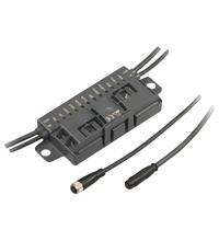
| Connection | Insulation piercing technology Yellow flat cable/black flat cable M12 round plug connector in accordance with EN 61076-2-101 LF type (4-pin, bushing contacts, screw lock, A-coded) Matching connector: LM type or similar LF type (4-pin, bushing contacts, screw lock, A-coded) Matching connector: LM type or similar |
| Mass | 260 g |
| Switching point | according to DIN EN 61131-2 0 (undamped) ≤ 0.5 mA 1 (damped) ≥ 2.0 mA |
| Mounting | 2 clips with ∅ 8 mm drill hole |
| Current | 2 A per output TB ≤ 40 °C: 6 A total TB ≤ 60 °C: OUT1+OUT2 max. 3 A, OUT3 max. 2 A |
| Note | The flat cable routing is designed for 100 actuation cycles |
| Cable length | 0.7 m (Inputs) , 1.5 m (X1, X2) |
| Rated operating current | ≤ 35 mA |
| Emitted interference | EN 61000-6-4:2007 |
| Noise immunity | EN 61000-6-2:2005, EN 61326-1:2006, EN 62026-2:2013 |
| Directive 2014/30/EU | EN 62026-2:2013 |
| Supply | from external auxiliary voltage U |
| Fieldbus standard | EN 62026-2:2013 |
| LED PWR | AS-Interface voltage; green LED green: voltage OK flashing green: address 0 or overload of sensor power supply or overload of outputs or external auxiliary voltage U missing |
| Voltage | ≥ (U - 0.5 V) |
| Current loading capacity | 500 mA , overload and short-circuit protected |
| Rated operating voltage | 26.5 ... 31.6 V from AS-Interface |
| UL File Number | E223772 "For use in NFPA 79 Applications only" |
| Number/Type | 3 electronic outputs, PNP, overload and short-circuit proof |
| Signal delay | < 1 ms (input/AS-Interface) |
| Input current | ≤ 8 mA (limited internally) |
| AS-Interface specification | V3.0 |
| LED AUX | ext. auxiliary voltage U ; dual LED green/red green: voltage OK red: reverse voltage |
| AS-Interface | EN 62026-2:2013 |
| MTBF | 110 a |
| Slave type | A/B slave |
| Required master specification | ≥ V2.1 |
| LED IN | switching state (input); 4 LED yellow |
| Input | EN 61131-2:2007 |
| Profile | S-7.A.E |
| IO code | 7 |
| ID code | A |
| ID1 code | 7 |
| ID2 code | E |
| D0 | IN1 OUT1 |
| D1 | IN2 OUT2 |
| D2 | IN3 OUT3 |
| D3 | IN4 - |
| P0 | Communication monitoring P0 = 0 monitoring = off, the outputs maintain the status if communication fails P0 = 1 monitoring = on, i.e. if communication fails, the outputs are deenergised (default settings) |
| P1 | Input filter P1 = 0 input filter on, pulse suppression ≤ 2 ms P1 = 1 input filter off (default settings) |
| P2 | Synchronous mode P2 = 0 synchronous mode on P2 = 1 synchronous mode off (default settings) |
| LED FAULT | error display; LED red red: communication error or address is 0 red flashing: overload of sensor power supply or overload of outputs or external auxiliary voltage U missing |
| Auxiliary voltage (output) | 20 ... 30 V DC PELV |
| LED OUT | Switching state (output); 3 LED yellow |

 Сравнение
 Избранное